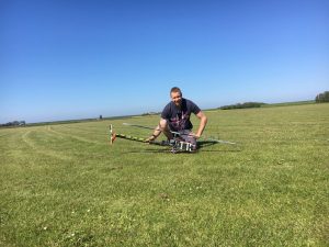
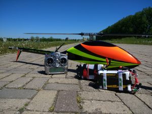
New power for the Three Dee Rigid II
It took me some time to make a decision on which lipo’s to buy. As can be read in my previous blog there were a couple of options. But my decision was made. The Henseleit TDR II needed the best available lipo’s and I went for quality. The SLS SPEED lipo’s 5100 mAh which are capable of 70C ( 350 Amps) should do the job. With these specs I think the battery will last longer, and can easily handle the extra power if I need it. The test report from elektromodellflug.de shows very impressive results for these new cells. So with the decision made, I installed these speed cells in my TDR II.
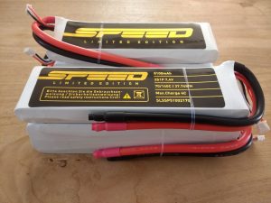
Unpacking the SPEED Lipo’s
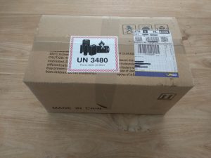
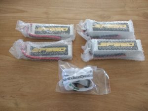
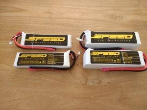
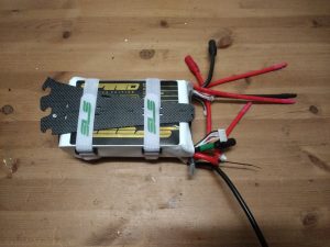
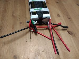
A couple of days later the box with lipo’s arrived. The delivery time was a total of two days due to the post coming from Germany to The Netherlands. As soon as the package arrived, I quickly unpacked the batteries for a visual inspection. Nicely packed! They are bigger in size as expected, but this is of course logical due the extreme high currents they can produce.
Mounting the Lipo’s in the TDR II
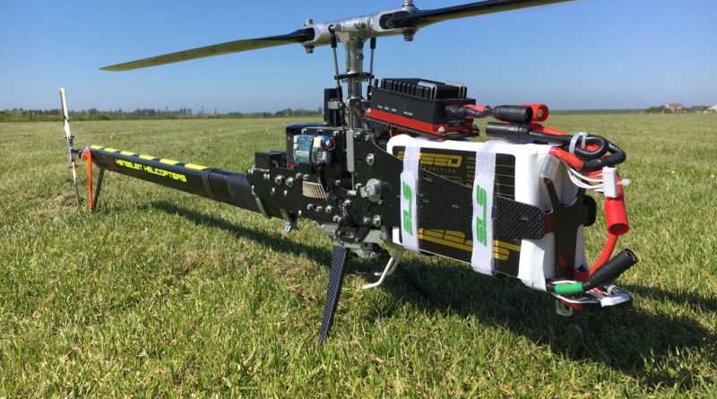
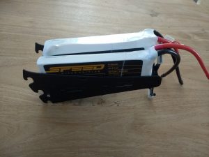
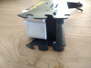
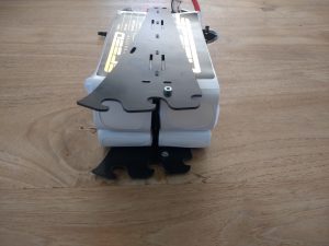
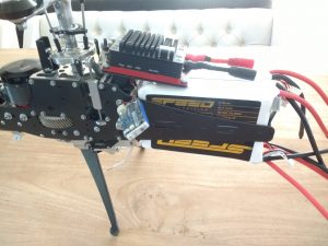
So the first impression is already very positive. Next step: put the batteries in the battery tray of the TDR II – and that is where I hit my first obstacle. They did not fit… The battery tray was not wide and long enough to fit the 2x 7s Lipo’s. By positioning the batteries on their side (instead of flat) in the tray they fit in the width, but in the length they are almost 1 cm too long.
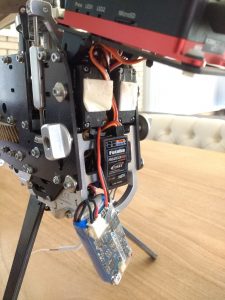
This left me no other option than to take the support plate out of the battery tray. Easy job and easily done. And yes, they fit perfectly in the battery tray.. but not in the helicopter. The electronics (BEC battery and the receiver) prevents the tray to position in their locking system. Only by taking the BEC system out the tray with the 5100mAh SPEED lipo’s fits.
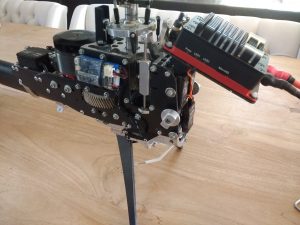
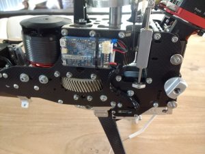
Re-positioning the BEC is again a bigger challenge due to the cable wiring. All the wires and servo’s are bound together and there is almost no space left. After some testing I decided the only logical position to mount the external backup BEC is on the side frame. But in order to do this all wires need to be re-positioned and all tie wraps cut and new wires sets need to be bound. And if that all is done, making sure that all the connectors are back in the right slot on the Vstabi Neo. However, there was no space to do that, and there is still no space to do this properly. But with some time, stress, pain in my fingers it was done (took at least 3 hours), landing gear wires Aux1, Aux2 and Aux3 where switched. And they all look the same. Tip for me next time to mark the connectors.
And now the TDR II is ready.. Not really. The lipo battary themselves need to be solded and get their connectors
- Making 2 packs
- Solding the 5s+2s together and make a 7s pack out of it
- Solding the AS150 connectors to the (5+2s) set pack
- And make for each 7s pack a own balancer connector instead of a 2s and 5s connector
Solding the battary packs
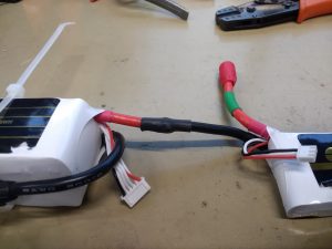
The wire at the lipo’s are 8AWG wires (8mm^2). A good powerful soldering tool is needed. And as a backup I have a propaan solder where the flame helps to heat up the connector. In order to prevent a short circuit make sure the wires can never touch each other unattended as well as the balancing connectors. This can by done through an easy way with a tie wrap or a rubber elastic band.
First step is to solder the connectors to the battery pack. First place the battery pack back in the tray in order to measure the right length and see if the wires are connected on the right way preventing a short circuit, wrong length of the cable or the wrong connector. I always use the AS150 connectors. The can handle the 150Amps but also have the advantage to have a anti spark in the connector.
Strip the connectors (6-8mm), put the shrink tube on the cable. I prefer to solder the connector and cable in a straight way, meaning they are positioned perfectly straight in line, battery lighing down on the perfect height while clamping the connector in a vise. This mikes is all much easier, the connector could be pre-heated with the flame of the propan solder iron and the the electric iron then can take over to solder the tin smoothly on the connector. Take your time, it takes some time to make the tin reach through the connector and also the bottom of the wire. Take your time for this.
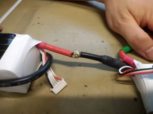
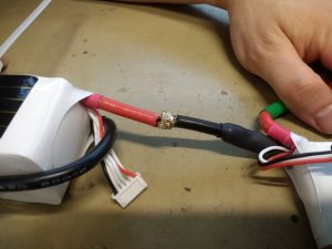
Next step. Strip the wires on both side (6-8mm), and don’t forget to put the heat shrink tube on the wire now! Now make the wiring interlock by softly connecting them and then slowly pull it out again. Don’t forget to put the heat shrink tube on the wire! You feel the friction of the small wires. Now push them together with your finger and start solding. Put a lot of tin on it and move your solding ion on all sides of the wire. This way you heat will be disapated evenly and makes the tin spread of the whole connection.
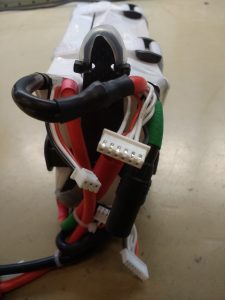
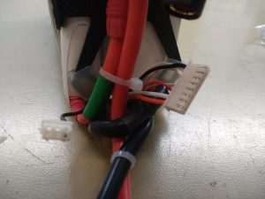
Almost done. Last thing to do (in my case) to make a new lipo balancer connector. I use the batteries in serie, but charging is done parallel. The reason for this is that my Orbit Micro charger can not handle 14s. So the batteries are then charged parallel and to prevent a wrong wiring of the 2s and 5s lipo’s I combined the balancer connector of the 2s and 5s together to a 7s connector.
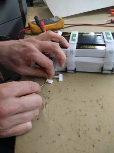
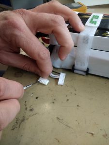
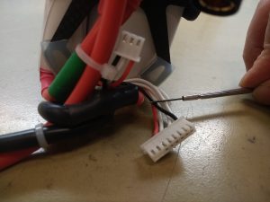
This is a relative easy job. You need a very small flat screwdriver to pinch back the lib of the connector. Then you can pull out the metal connector and stick this back in the new 7s (8 holes) connector. I count from plus (red) to minus starting with the red wire of the 2s Lipo.
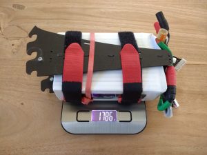
The result:
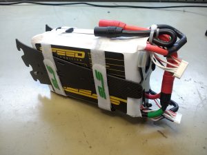
A perfect 2x 7s Lipo pack which can be used as 14s, and charging in a 7s2p setup.
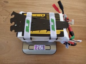
Ready?
Everything is set. Battery pack is solded, connectors are good, the battery tray fits in the helicopter and all servo’s etc work fine. V-stabi ready. I was told to perform 3 slow flights before reaching the maximum power. Our garden was luckily large enough to just hoover.
The checklist done. What can go wrong? Ready to test the brand new lipo’s on the flight field. But my canopy on the helicopter and…… &%$@#$!#$%%$#
I forgot that not only were there batteries much larger that they could not fit the battery tray, but they were so large that they could not fit the small canopy anymore. I tried out every possible way to squeeze them in the canopy, but I did not succeed.
Nope, that won’t do…
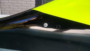
Which options did I have left? Drill some new mounting holes in the canopy. This way it will fit…
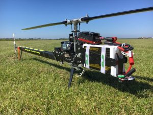
Now it was time to let the beast out, and see how much performance this new battery pack brought to the TDR II.
And yes, the power is amazing, the whole machine is just pure fun. Now I can fly 2 battery packs a day instead of one. Loving the summer on the airfield.

